
Reactive compensation controller
Date:2018/1/8 9:52:35 / Popularity:
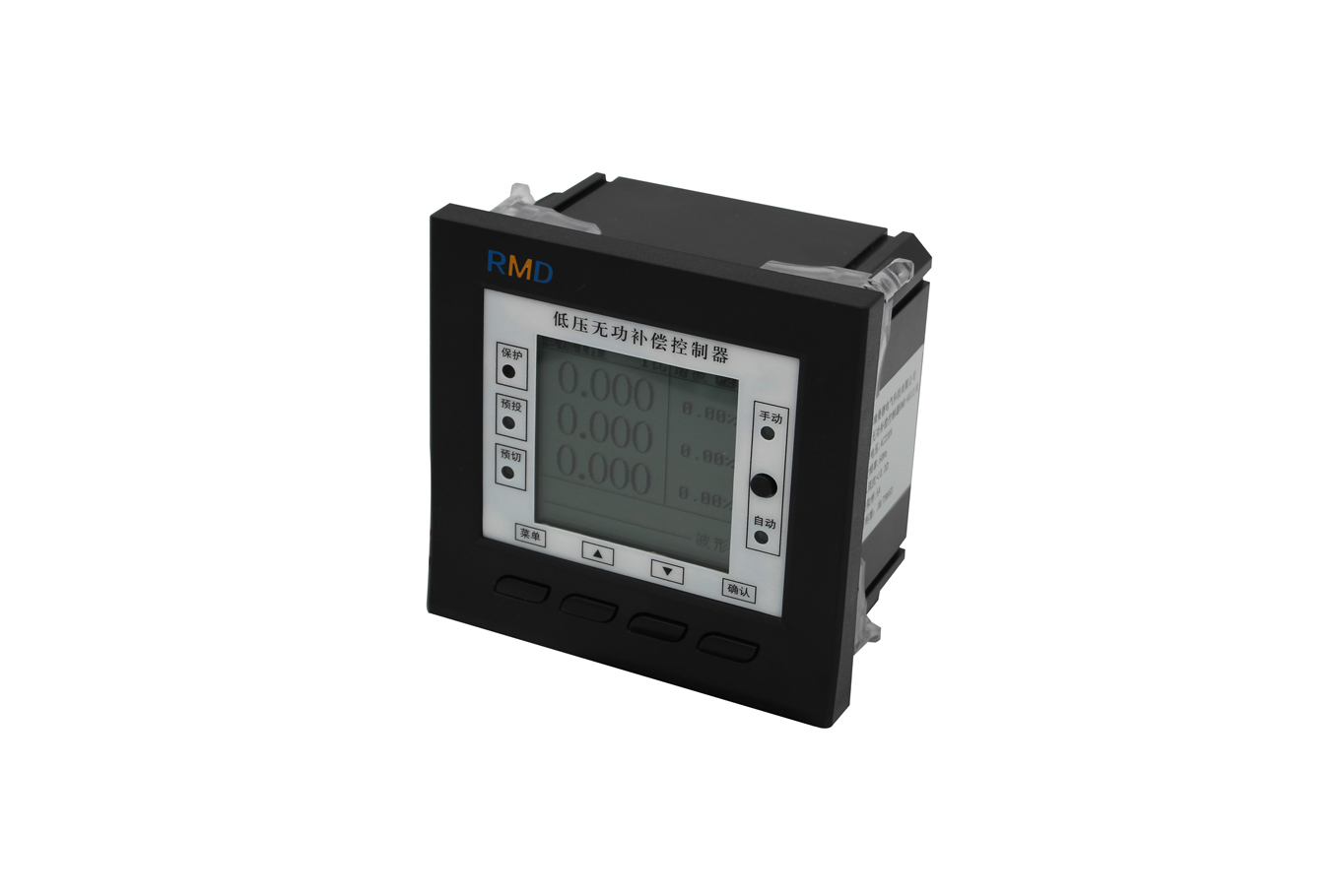
First, the product overview
RMD series reactive power compensation controller is based on reactive power as a sampling physical compensation controller. The controller can reliably operate in harsh conditions such as large harmonics, non-sinusoidal current, strong interference and other adverse grid environment, the advanced unique word adaptation function to ensure the safe use of power capacitors, the real power capacitor to achieve safe and effective improvement Power factor of the grid.
Second, the model description

Third, the performance characteristics
n all digital design, using AC sampling algorithm, human-machine interface using large-screen LCD Chinese liquid crystal display
n Adhering to the people-oriented design concept, modular assembly, the appearance of streamline design
n Real-time display voltage, current, power factor, active power, reactive power, voltage total harmonic distortion rate, current total harmonic distortion rate, frequency, temperature, capacitance output display and switch the state alarm and other information
n with 12/18/24 control output, support for three-phase compensation, phase compensation, comprehensive compensation program, the use of dynamic and static two compensation methods, with manual compensation and automatic compensation of two working methods
n Capacitor switching control program supports isosceles, coding (1: 2,1: 2: 3,1: 2: 4: 8 ...) and fuzzy control switching mode
n sampling physical amount of reactive power, with harmonic measurement and protection
n with RS-485 standard bus interface, support for Modbus-RTU communication protocol, suitable for complete sets of intelligent power distribution cabinet, smart box variable data acquisition, reactive power compensation
Technical indicators
l standards meet JB / T9663-199 requirements
l signal input
Rated current AC 5A (current transformer secondary side)
Rated voltage 220V / 380V
Frequency 50 / 60Hz
l Auxiliary power supply
Working range AC 220V ± 20%
l measuring range
Power factor lags from 0.200 to 0.200 ahead of schedule
l measurement accuracy
Voltage 0.5 level
Current 0.5 level
Power factor 1.0 level
Active power 1.0 level
Reactive power level 1.0
Frequency ± 0.1Hz
l communication function
RS-485 communication Modbus-RTU protocol, baud rate
4800 ~ 38400bps (no parity bit)
l control output
Output circuit 10 or 12 Road
Relay output dry node method, AC 250V / 5 resistance
Sex
Level output DC 12V 30mA / branch
l reliability
Mean time between failures ≥ 250000h
Environment
Working temperature -20 ℃ ~ +60 ℃
Storage temperature -40 ℃ ~ +70 ℃
Altitude ≤ 2500m
Ambient conditions No corrosive atmosphere, none
Conductive dust, non-flammable and explosive medium
Quality exists, installation site without violent vibration, no rain and snow erosion
l Dimensions
Face frame size (mm) 120 × 120
Hole size (mm) 113 × 113
Specifications selection
Function model | RMD-KF24A/B | RMD-KG24A/B | |
Measurement function | Power factor | √ | √ |
Voltage | √ | √ | |
Current | √ | √ | |
Active power | √ | √ | |
Reactive power | √ | √ | |
frequency | √ | √ | |
Voltage total harmonic distortion rate | √ | √ | |
Current total harmonic distortion rate | √ | √ | |
Protective function | Over and under pressure | √ | √ |
Over owed | √ | √ | |
Over deficiencies | √ | √ | |
harmonic | √ | √ | |
Loss of pressure release protection | √ | √ | |
Harmonic distortion exceeds limit | √ | √ | |
Communication function | RS-485 communication | √ | √ |
Control output | Output circuit number | 12/18/24 | 12/18/24 |
A: Relay output (static) | √ | √ | |
B: 12VDC level output (dynamic) | √ | √ | |
Compensation method | Total complement | √ | √ |
Points up | — | √ | |
Capacitor switching mode | Isovolence / coding / blurring | Isovolence / coding / blurring | |
Display method | LCD | LCD | |
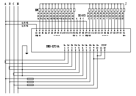
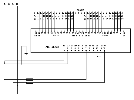
Fourth, the typical connection
1. A total of 12 Road + points complement 4 Road program, static type wiring
Note: When the contactor coil is 220V, the J point connects to the N phase. When the contactor coil is 380V, the J point connects to the B phase or C phase.
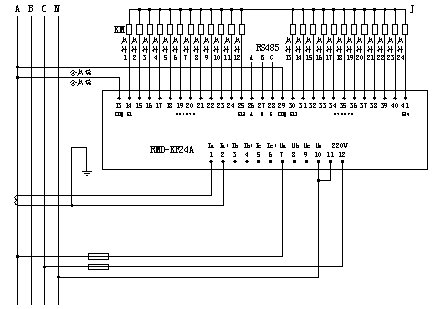
2. A total of 24 programs, static type wiring
Note: When the contactor coil is 220V, the J point connects to the N phase. When the contactor coil is 380V, the J point connects to the B phase or C phase.
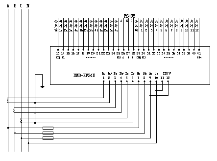
3. Complement a total of 12 + points up 4 Road program, dynamic wiring
4. Complement a total of 24 programs, dynamic wiring
Fifth, the installation size

