Reactive power compensation filter device
Date:2018/1/8 9:24:41 / Popularity:
Reactive power compensation filter device
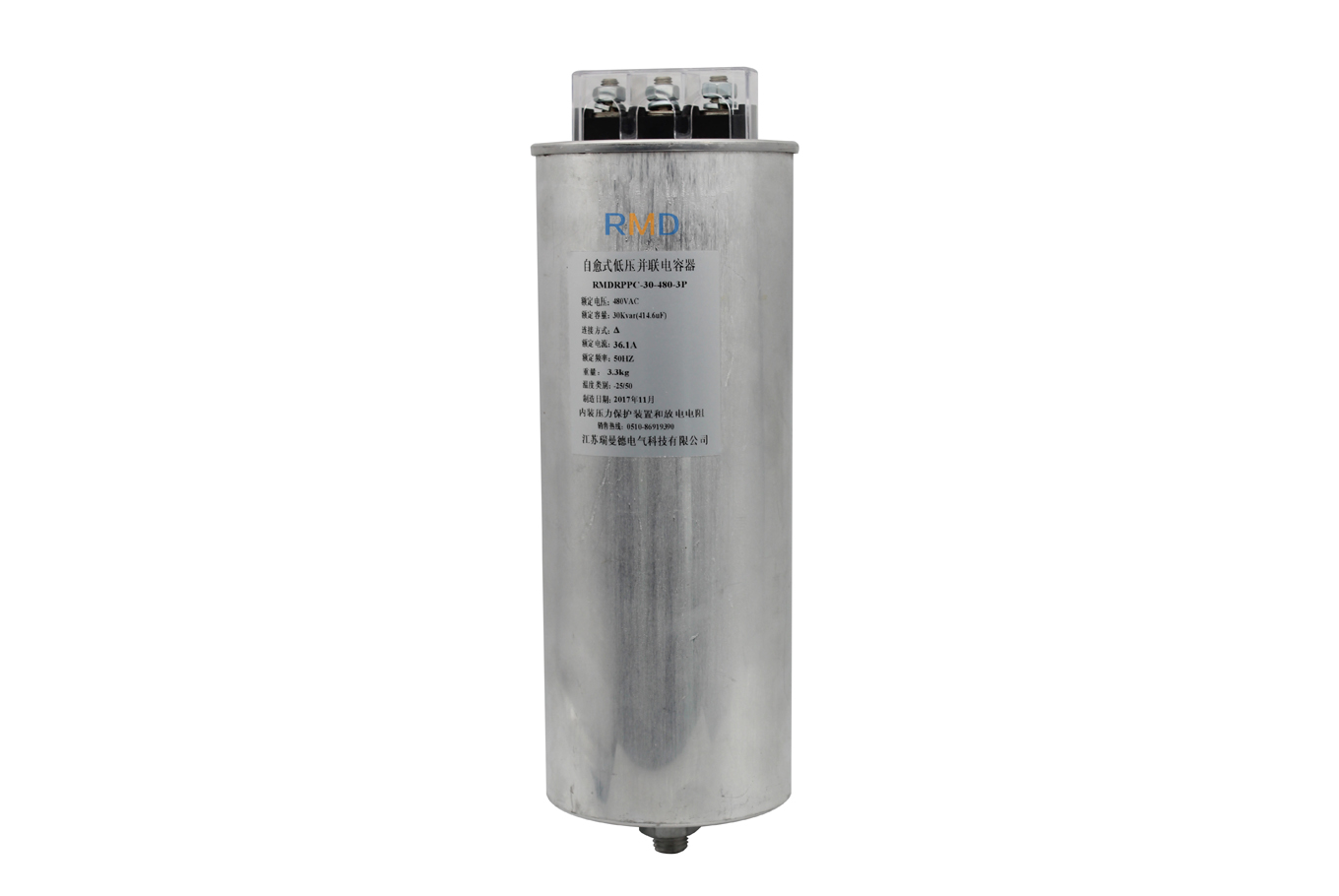
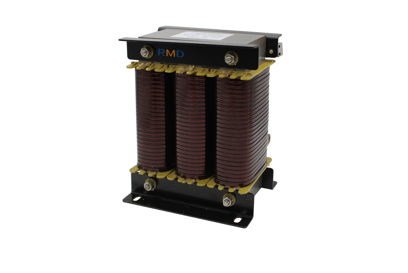
First, the product overview
Reactive power compensation filter device is divided into RMDG modular and (T) modular two.
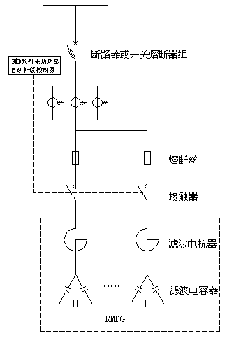
RMDG component reactive power compensation filter device is a certain degree of reactance filter reactance and a certain capacity of the filter capacitor for the appropriate proportion to configure the filter loop, so as to achieve reactive power compensation, power filtering and harmonic suppression purposes. RMDG components by the filter reactor and filter capacitor components, excluding contactor, knife switch and other components.
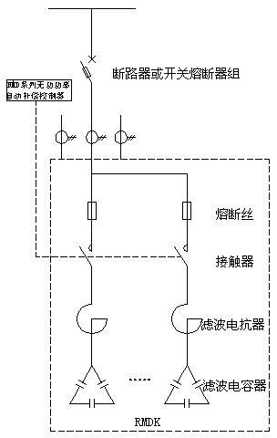
(T) modular reactive power compensation filter device is composed of filter reactor, filter capacitor, contactor, knife switch, bus system, high temperature wire and terminals and other components through a combination of professional structural design. Can be suitable for a variety of types of cabinet, the package is very convenient.
Second, the performance characteristics
n miniaturization of products, simple device structure, flexible parameter adjustment
n assembly flexibility, free assembly as needed
n According to the filter harmonic elimination or safety compensation required for the selection of reactance
n bus structure, safe and reliable, easy to connect
n capacitance with self-healing function, high reliability
Inhibit the 3rd, 5th, 7th and 9th harmonics to avoid resonance
n strong traffic, suitable for a variety of capacitor compensation cabinets, supporting convenient
n 9μm metal polypropylene film capacitor, the dielectric strength and electrical weakness far higher than similar products in the industry to ensure the safe and reliable operation.
n contactors, fuse switches and fuses all use the German Muller and Siemens products
Third, technical indicators
RPPLReactor | |
standard | IEC76、VDE0550/0532 |
Rated voltage | 400V AC |
Rated frequency | 50Hz |
Reactance factor | 5.5%,7%,12.5% |
Overcurrent capability | 1.8In(moment),1.1In(long) |
Linearity | 1.8In≥0.95 |
Inductance deviation | ±3% |
Ambient temperature | -25℃~+50℃ |
Temperature protection | 110℃ normally closed contact off |
Heat-resistant grade | F grade or H grade(According to the requirements can be achieved) |
Degree of protection | IP00,Indoor installation |
RPPCCapacitor | |
standard | IEC60831-1+2,GB/T12747-2004 |
Capacitance deviation | -5%~+10% |
Dielectric loss tangent | tgδ≤0.0002 (50Hz/Un measuring) |
Total loss tangent | tgδ≤0.001(50Hz/Un measuring) |
Rated frequency | 50Hz |
Extreme pressure | 2.15Un/5S(Un For the rated voltage) |
Pole shell pressure | 3600V AC/2S |
The maximum allowable over-voltage | 1.10UnVAC——24h/8h 1.15UnVAC——24h/30min 1.20UnVAC——5min 1.30UnVAC——1min(Un Capacitor rated voltage) |
The maximum allowable current | ≤1.3In |
Discharge performance | After 1.41Un power down, discharge within 3min to 75V or less |
safety | Meet the requirements of destructive test in IEC60831-1 + 2 and GB / T12747.2-2004 |
Average life | 115000h |
cool down | Natural cooling or forced air cooling |
humidity | ≤95% |
Altitude | ≤1000m |
Temperature category | -20/D |
storage temperature | -40℃~70℃ |
Degree of protection | IP20,Indoor installation |
Installation and grounding | M12 or M16 bolting pan |
Dielectric | High-quality polypropylene film |
Perfusion material | Inert gas or nitrogen (N2) or gas mix Resln |
Bottom bolt installation torque | 12N.m |
Lead to the terminal installation torque | 5N.m |
Fourth, the model description

Remark: Reactance coefficient is through the rational matching of reactance reactance and capacitor capacitance, making the reactive power compensation filter device appear capacitive at the fundamental frequency to compensate reactive power. At the harmonic frequency, it shows sensibility and maximally Reduce the risk of resonance, and because of its low resistance, effectively suppress and filter out harmonics.
Reactance coefficient of choice: For the 3rd harmonic, choose 14%; For 5,7 times and above higher harmonics, choose 5.5%; Less harmonics can choose 7% as a safety compensation.
Specifications selection
A, series, for 400V 50Hz power system, three-phase, △ connection
model | Capacitor voltage(V) | DimensionsW×D×H(mm) | Installation dimensions(mm) | |
RMDK10-P5.5/400 | 10 | 480 | 600×600×350 | 560×560 |
RMDK12.5-P5.5/400 | 12.5 | 480 | 600×600×350 | 560×560 |
RMDK15-P5.5/400 | 15 | 480 | 600×600×350 | 560×560 |
RMDK20-P5.5/400 | 20 | 480 | 600×600×350 | 560×560 |
RMDK25-P5.5/400 | 25 | 480 | 600×600×350 | 560×560 |
RMDK30-P5.5/400 | 30 | 480 | 600×600×350 | 560×560 |
RMDK40-P5.5/400 | 40 | 480 | 600×600×350 | 560×560 |
RMDK40-P5.5/400 | 50 | 480 | 600×600×350 | 560×560 |
RMDK60-P5.5/400 | 60 | 480 | 600×600×350 | 560×560 |
RMDK80-P5.5/400 | 80 | 480 | 600×600×350 | 560×560 |
RMDK10-P7/400 | 10 | 480 | 600×600×350 | 560×560 |
RMDK12.5-P7/400 | 12.5 | 480 | 600×600×350 | 560×560 |
RMDK15-P7/400 | 15 | 480 | 600×600×350 | 560×560 |
RMDK20-P7/400 | 20 | 480 | 600×600×350 | 560×560 |
RMDK25-P7/400 | 25 | 480 | 600×600×350 | 560×560 |
RMDK30-P7/400 | 30 | 480 | 600×600×350 | 560×560 |
RMDK40-P7/400 | 40 | 480 | 600×600×350 | 560×560 |
RMDK50-P7/400 | 50 | 480 | 600×600×350 | 560×560 |
RMDK60-P7/400 | 60 | 480 | 600×600×350 | 560×560 |
RMDK80-P7/4000 | 80 | 480 | 600×600×350 | 560×560 |
RMDK10-P14/400 | 10 | 525 | 600×600×350 | 560×560 |
RMDK12.5-P14/400 | 12.5 | 525 | 600×600×350 | 560×560 |
RMDK15-P14/400 | 15 | 525 | 600×600×350 | 560×560 |
RMDK20-P14/400 | 20 | 525 | 600×600×350 | 560×560 |
RMDK25-P14/400 | 25 | 525 | 600×600×350 | 560×560 |
RMDK30-P14/400 | 30 | 525 | 600×600×350 | 560×560 |
RMDK40-P14/400 | 40 | 525 | 600×600×350 | 560×560 |
RMDK50-P14/400 | 50 | 525 | 600×600×350 | 560×560 |
RMDK60-P14/400 | 60 | 525 | 600×600×350 | 560×560 |
RMDK80-P14/400 | 80 | 525 | 600×600×350 | 560×560 |
Note: (T) is a dynamic compensation module, other specifications can be ordered on request, the size is for reference only, the actual size of the user needs or different placement to determine
Second, RMDG series, suitable for 400V 50Hz power system, three-phase, delta connection
model | Compensation capacity(kVar) | Combination way | |
Capacitor model | Reactor model | ||
RMDG10-P5.5/400 | 10 | RPPC-10-480-3P | RPPL-10/400-5.5% |
RMDG12.5-P5.5/400 | 12.5 | RPPC -12.5-480-3P | RPPL-12.5/400-5.5% |
RMDG15-P5.5/400 | 15 | RPPC -15-480-3P | RPPL -15/400-5.5% |
RMDG20-P5.5/400 | 20 | RPPC -20-480-3P | RPPL -20/400-5.5% |
RMDG25-P5.5/400 | 25 | RPPC -25-480-3P | RPPL -25/400-5.5% |
RMDG30-P5.5/400 | 30 | RPPC -30-480-3P | RPPL -30/400-5.5% |
RMDG40-P5.5/4000 | 40 | RPPC -20-480-3P×2 | RPPL -40/400-5.5% |
RMDG50-P5.5/400 | 50 | RPPC -25-480-3P×2 | RPPL -50/400-5.5% |
RMDG60-P5.5/400 | 60 | RPPC -30-480-3P×2 | RPPL -60/400-5.5% |
RMDG80-P5.5/400 | 80 | RPPC -20-480-3P×4) | RPPL -80/400-5.5% |
RMDG10-P7/400 | 10 | RPPC -10-480-3P | RPPL -10/400-7% |
RMDG12.5-P7/400 | 12.5 | RPPC -12.5-480-3P | RPPL -12.5/400-7% |
RMDG15-P7/400 | 15 | RPPC -15-480-3P | RPPL -15/400-7% |
RMDG20-P7/4000 | 20 | RPPC -20-480-3P | RPPL -20/400-7% |
RMDG25-P7/400 | 25 | RPPC -25-480-3P | RPPL -25/400-7% |
RMDG30-P7/400 | 30 | RPPC -30-480-3P | RPPL -30/400-7% |
RMDG40-P7/400 | 40 | RPPC -20-480-3P×2(台) | RPPL -40/400-7% |
RMDG50-P7/400 | 50 | RPPC -25-480-3P×2(台) | RPPL -50/400-7% |
RMDG60-P7/400 | 60 | RPPC -30-480-3P×2(台) | RPPL -60/400-7% |
RMDG80-P7/400 | 80 | RPPC -20-480-3P×4(台) | RPPL -80/400-7% |
RMDG10-P14/400 | 10 | RPPC -10-525-3P | RPPL -10/400-12.5% |
RMDG12.5-P14/400 | 12.5 | RPPC -12.5-525-3P | RPPL -12.5/400-12.5% |
RMDG15-P14/400 | 15 | RPPC -15-525-3P | RPPL -15/400-12.5% |
RMDG20-P14/400 | 20 | RPPC -20-525-3P | RPPL -20/400-12.5% |
RMDG25-P14/400 | 25 | RPPC -25-525-3P | RPPL -25/400-12.5% |
RMDG30-P14/400 | 30 | RPPC -30-525-3P | RPPL -30/400-12.5% |
RMDG40-P14/400 | 40 | RPPC -20-525-3P×2(台) | RPPL -40/400-12.5% |
RMDG50-P14/400 | 50 | RPPC -25-525-3P×2(台) | RPPL -50/400-12.5% |
RMDG60-P14/400 | 60 | RPPC -30-525-3P×2(台) | RPPL -60/400-12.5% |
RMDG80-P14/400 | 80 | RPPC -20-525-3P×4(台) | RPPL -80/400-12.5% |
Note: Other specifications can be ordered on request.
Reactance capacitor specifications
First, PFC capacitor size table
model | Rated voltage(V) | Rated Capacity(kVar) | DimensionsΦD×H(mm) | Installation method |
RPPC-10-480-3P | 480 | 10 | 65×240 | M12×16 |
RPPC -12.5-480-3P | 480 | 12.5 | 76×240 | M12×16 |
RPPC -15-480-3P | 480 | 15 | 86×240 | M12×16 |
RPPC -20-480-3P | 480 | 20 | 96×240 | M16×25 |
RPPC -25-480-3P | 480 | 25 | 106×240 | M16×25 |
RPPC -30-480-3P | 480 | 30 | 116×240 | M16×25 |
RPPC -10-525-3P | 525 | 10 | 76×240 | M12×16 |
RPPC -12.5-525-3P | 525 | 12.5 | 86×240 | M12×16 |
RPPC -15-525-3P | 525 | 15 | 86×240 | M12×16 |
RPPC -20-525-3P | 525 | 20 | 96×240 | M12×16 |
RPPC -25-525-3P | 525 | 25 | 86×290 | M12×16 |
RPPC -30-525-3P | 525 | 30 | 116×290 | M16×25 |
二、FR reactor specifications table
model | Reactance factorP(%) | DimensionsL×W×H(mm) | Installation dimensionsE×F(mm) |
RPPL-10/400-5.5% | 5.5 | 195×120×155 | 100×70 |
RPPL-12.5/400-5.5% | 5.5 | 200×150×150 | 100×85 |
RPPL-15/400-5.5% | 5.5 | 210×170×150 | 100×90 |
RPPL -20/400-5.5% | 5.5 | 240×185×180 | 100×100 |
RPPL -25/400-5.5% | 5.5 | 250×190×180 | 100×100 |
RPPL -30/400-5.5% | 5.5 | 250×190×180 | 100×100 |
RPPL -40/400-5.5% | 5.5 | 260×200×200 | 100×110 |
RPPL -50/400-5.5% | 5.5 | 280×210×205 | 100×115 |
RPPL -60/400-5.5% | 5.5 | 300×220×250 | 120×120 |
RPPL -80/400-5.5% | 5.5 | 300×230×260 | 120×130 |
RPPL -10/400-7% | 7 | 235×160×190 | 100×90 |
RPPL -12.5/400-7% | 7 | 235×170×190 | 100×100 |
RPPL -15/400-7% | 7 | 200×160×160 | 150×95 |
RPPL -20/400-7% | 7 | 240×170×175 | 150×100 |
RPPL -25/400-7% | 7 | 260×160×180 | 150×100 |
RPPL -30/400-7% | 7 | 280×160×195 | 150×100 |
RPPL -40/400-7% | 7 | 270×190×210 | 150×115 |
RPPL -50/400-7% | 7 | 285×200×235 | 180×120 |
RPPL -60/400-7% | 7 | 270×210×280 | 180×120 |
RPPL -80/400-7% | 7 | 310×220×290 | 180×140 |
RPPL -10/400-14% | 14 | 260×175×220 | 120×95 |
RPPL -12.5/400-14% | 14 | 260×190×170 | 120×105 |
RPPL -15/400-14% | 14 | 260×195×175 | 120×105 |
RPPL -20/400-14% | 14 | 275×210×210 | 120×110 |
RPPL -25/400-14% | 14 | 280×210×210 | 120×115 |
RPPL -30/400-14% | 14 | 290×220×230 | 120×120 |
RPPL -40/400-14% | 14 | 310×230×250 | 120×130 |
RPPL -50/400-14% | 14 | 320×235×260 | 120×135 |
RPPL -60/400-14% | 14 | 350×240×295 | 120×140 |
RPPL -80/400-14% | 14 | 360×250×300 | 120×150 |
Sixth, the installation size
n RMDK

n RMDG

FR reactor

PFC capacitor
Typical application wiring diagram

Installation advice and precautions
First, filter compensation cabinet capacitor and reactor temperature characteristics and ventilation requirements
n The applicable ambient temperature class for our capacitors is -20 ° C / D, ie the minimum ambient temperature is -20 ° C; the ambient temperature is limited to Class D. Cabinets around the capacitor, the maximum ambient temperature of 55 ℃; average maximum within 24 hours of 45 ℃; the highest average of 35 ℃ within a year. (See Annex 1 for details)
Annex 1: Low-voltage capacitor standards
GB/T 12747.1-2004/IEC 60831-1:1996 | |||
"The nominal voltage 1KV and below AC power system with self-healing shunt capacitor" standard | |||
Table 1 shows the upper limit of the temperature range of the letter code | |||
Code | Ambient temperature / ℃ | ||
highest | The highest average within 24h | Average highest in 1 year | |
A | 40 | 30 | 20 |
B | 45 | 35 | 25 |
C | 50 | 40 | 30 |
D | 55 | 45 | 35 |
n Our reactor insulation class F or H grade, the normal operating temperature of 80 ℃ ~ 130 ℃, according to the heat 4 ~ 6W / kVar calculation, namely:
1 surface 200kVar filter compensation cabinet reactor heat is 800 ~ 1200W.
1 surface 300kVar filter compensation cabinet reactor heat is 1200 ~ 1800W.
n filter heat compensation calculation cabinet: (taking into account the reactor, capacitors, contactors, fuses and cables fever) in accordance with the heat 6 ~ 8W / kVar calculation, namely:
1 surface 200kVar filter compensation cabinet reactor heat is 1200 ~ 1600W.
1 surface 300kVar filter compensation cabinet reactor heat 1800 ~ 2400W.
n Fan ventilation calculation:
QF = Pw × 3.1 / ΔT
QF - ventilation, unit: m3 / H (cubic meters / hour)
Pw - the total heat components inside the cabinet, unit: W (watts)
△ T - temperature inside the cabinet, according to 10 ℃, unit: K
example:
200kVar filter compensation cabinet ventilation 372 ~ 496 m3 / H, take not less than 500 m3 / H.
300kVar filter compensation cabinet ventilation 558 ~ 744 m3 / H, take not less than 750 m3 / H.
n Considering the reliability of the system, at least two ventilation fans must be installed in each filter compensation cabinet. When one of the fans fails to stop running, the ventilation rate of the other fan shall meet the ventilation requirement calculated above.
n on the cooling air inlet and outlet
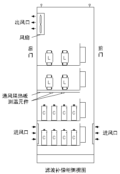
It is recommended to arrange the air inlet in the lower part of the front door and the rear door of the filter compensation cabinet, and the air outlet is arranged on the upper part of the back door of the cabinet or the top of the cabinet. The airway goes in and out.
Second, install the filter cabinet cooling recommendations
n Reactor and capacitor should be far away from the heat to avoid high temperature reactor heat roasted capacitor. It is recommended to install all the capacitors on the bottom of the cabinet, one or two layers can be arranged. Reactor installed in the capacitor above, you can arrange one or two layers. At the same time, to avoid thermal radiation reactor directly shines on the capacitor level.
n filter compensation cabinet to be ventilated fan to install adequate ventilation, the number of device fans at least 2 units, and 1 fan ventilation to meet the cooling ventilation requirements, the fan start and stop can be designed to automatically control The starting temperature is 40 ° C near the capacitor inside the cabinet, and the stop temperature is 30 ° C near the capacitor inside the cabinet, meanwhile, the air passage should be designed to enter the lower part of the wind and exit the wind.
n temperature monitoring measures
In the filter compensation cabinet, at least two temperature monitoring test points are installed, it is recommended to install in the vicinity of the capacitor. When detected near the capacitor temperature reaches 45 ℃ to alarm, to 55 ℃ to remove all the filter compensation unit, to avoid excessive temperature damage capacitors. Removal of capacitor operation using temperature monitor control of several intermediate relays, relay contacts by the intermediate control of each capacitive contactor.
Third, the installation diagram