
SCR cut-off switch
Date:2018/1/8 9:17:47 / Popularity:
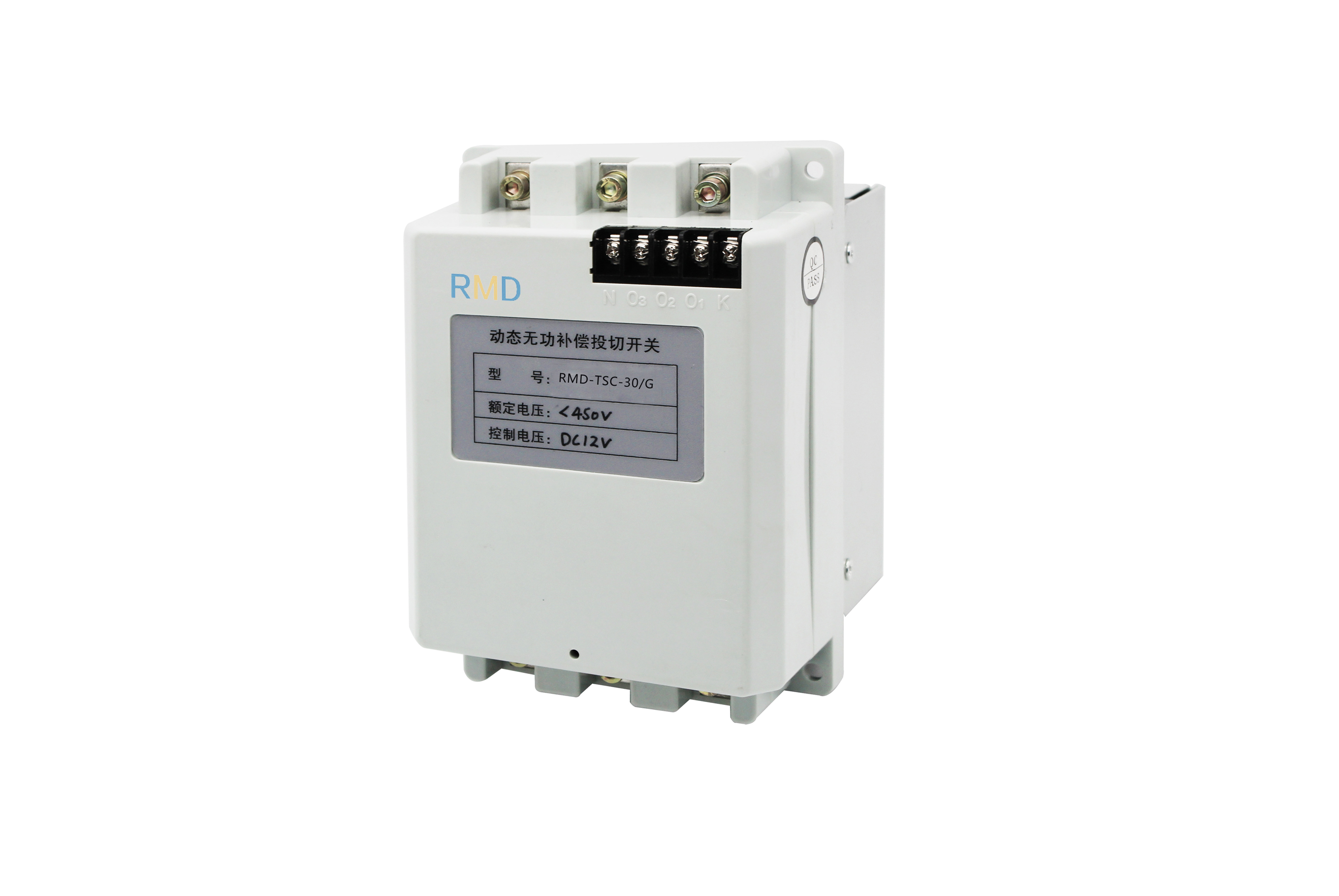
SCR cut-off switch
First, the product overview
Rapid fluctuations in the grid load continues to increase, the traditional contactor, composite switching capacitor bank, has been unable to meet the demand for reactive power compensation. Dynamic switching using switching power supply electronic device response speed of less than 20ms, to meet the rapidly fluctuating load reactive power compensation requirements, the main applications and spot welding, rolling and other rapid fluctuations in load.
Second, the model description
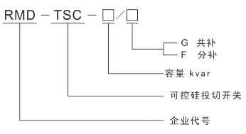
Third, the performance characteristics
n products using high-power anti-parallel thyristor modules, optical isolation circuit, trigger circuit, protection circuit and cooling device
n zero-crossing trigger technology, switching no current, no over-voltage
n switch response speed is less than 20ms
n Allow frequent switching the use of the number of not less than 300,000 times
n using temperature control technology, reliable assurance of SCR within the specified temperature range
n trigger protection circuit using anti-jamming design, effectively prevent false triggering
n switching module overload, over-temperature protection
n compact size, structural design is reasonable, easy and flexible wiring installation
Technical indicators
l rated voltage 230V, 400V
l control capacitor ≤ 60kVar, ≤ 3 × 20kVar
l control voltage DC12V
l control current 20mA
l Inrush current ≤1.8In
l elevation ≤ 2000m
l Ambient temperature -25 ℃ ~ +55 ℃
l Relative humidity ≤90%
l no harmful gas around the environment, no easy
Explosive items should have good
Good ventilation, as installed
Cabinet, ventilation equipment should be installed
Fourth, the specification selection
model | DimensionsL×W×H(mm) | Installation dimensionsa×b(mm) | |
Three-phase total complement | |||
HY-TSC-1-15 | 15 | 114×170 | image1 |
HY-TSC-1-30 | 30 | 114×170 | image1 |
HY-TSC-1-40 | 40 | 148×204 | image2 |
HY-TSC-1-50 | 50 | 148×204 | image2 |
HY-TSC-1-60 | 60 | 148×204 | image2 |
Single-phase points up | |||
HY-TSC-2-15 | 15 | 114×170 | image1 |
HY-TSC-2-30 | 30 | 114×170 | image1 |
HY-TSC-2-45 | 45 | 148×204 | image2 |
HY-TSC-2-60 | 60 | 148×204 | image2 |
Note: Other specifications can be ordered on request
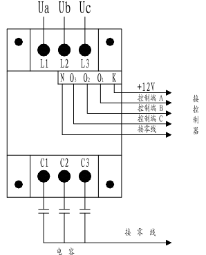
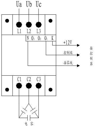
Fifth, the typical connection
n single-phase sub-patch wiring diagram
n A total of three-phase wiring diagram
Sixth, the installation size
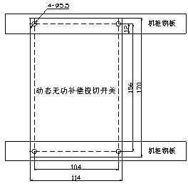
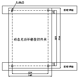
(Figure 1) Installation dimensions below 30kVar (Figure 2) Installation dimensions above 60kVar 30kVar or above
